BIOMASS COGENERATION
CLEAN AND SUSTAINABLE ENERGY SOLUTIONS
Acora has long thought the area of biomass for co-generation has had tremendous potential for our clients. We have been watching the developments in this area very carefully and feel we have found the right partner in Fortes, – proven – scalable – high efficiency – manufactured to comply with Australasian regulations.
Sawmills produce Biomass and use heat, so the combinations used with the Fortes system fit perfectly. Convert the biofuel to Syngas and from this generate electricity to use on site and the heat is used in the timber drying process.
TECHNOLOGICAL PROCESS
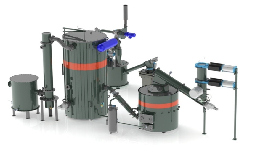
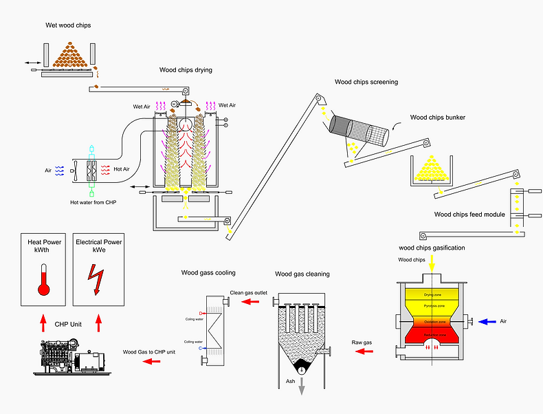
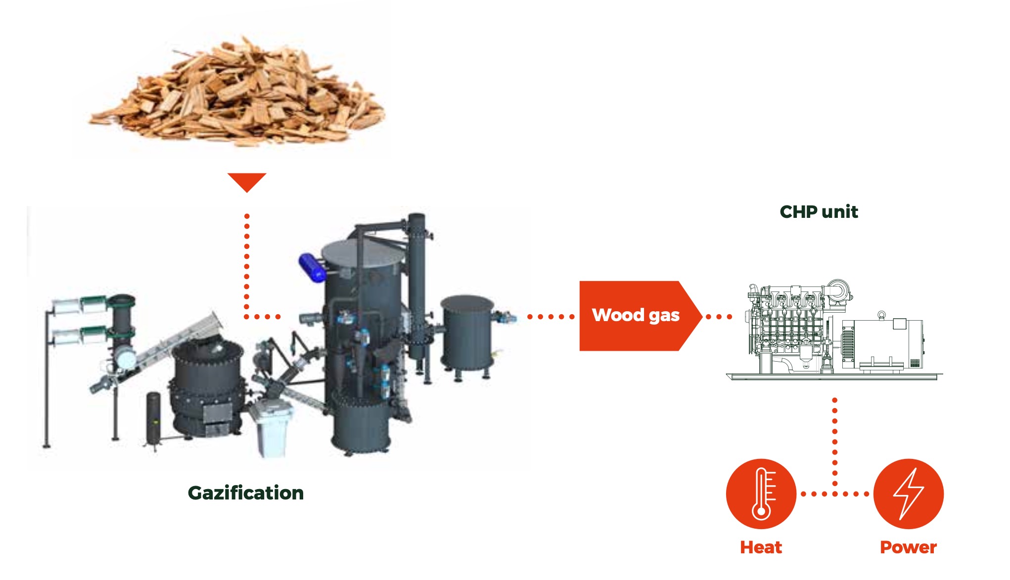
From the warehouse, the wood chips are automatically fed to the chain conveyor by means of moving floor sliders and further to the wood chip dryer. After the drying process, the wood chips are moved by a conveyor to a wood chip sieve, from which the fractions unnecessary for the gasification process are separated. Wood chips are then transported to the wood chip bunker (storage) by a chain conveyor. The screw conveyors of the wood chip bunker deliver the wood chips to the gasification equipment upon request of gasifier. Wood gas produced in gasifier is purified and cooled before delivered to CHP unit. To ensure safe overall operation of equipment, all process is fully automated
IN TIMES OF FUNDAMENTAL CHANGES IN ENERGY POLICIES, WE NEED ALTERNATIVE, ENVIRONMENTALLY FRIENDLY AND AFFORDABLE SOURCES OF ENERGY. THE TECHNOLOGY USED TO GENERATE POWER FROM WOOD INCREASES WOOD ENERGY VALUE MANY TIMES COMPARED TO CONVENTIONAL COMBUSTION, SIGNIFICANTLY ENHANCING EFFICIENT USAGE OF LOCALLY AVAILABLE RENEWABLE RESOURCES.
BIOMASS COGENERATION
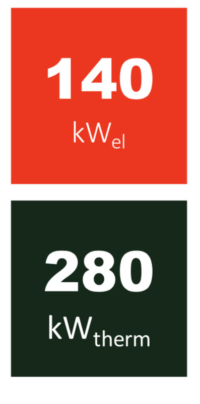
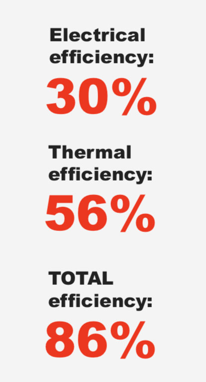
FORTES has developed highly efficient technology that transforms biomass into wood gas (Syngas) used to produce electricity and heat through the use of engine and generator system. Capacity for one unit is 140 kWel /280 KW therm power.
FORTES installs power plants integrating full cycle of technologies – storage, drying and supply of wood chips, wood gasification, and cogeneration where heat and electricity are produced.
WOOD GASIFICATION AND COGENERATION
GAS GENERATOR
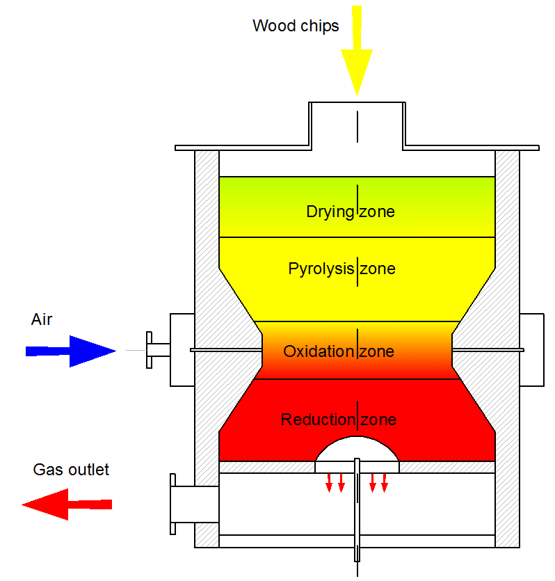
Convert solid wood chips to wood gas in the following way:
- In the drying zone, the material is completely dried by heat.
- Under the influence of heat in the pyrolysis process, wood chips decompose into charcoal and gaseous products. This process produces tar, which is partially burned in the oxidation zone. The pyrolysis process is oxygen-free and reaches a temperature of 200- 550°C.
- Oxidation of charcoal with oxygen and partial combustion of tar and gaseous products takes place in the oxidation zone. This process takes place at high temperatures, reaching up to 1200°C and above.
- In the reduction zone, the charcoal reacts with carbon dioxide and water to form a flammable gas mixture of carbon monoxide and hydrogen. The process takes place at a temperature of 700-750°C.
AIR PREHEATER
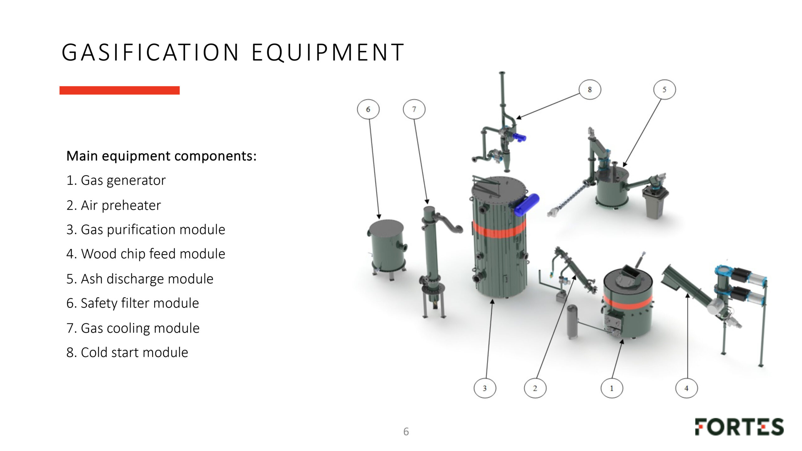
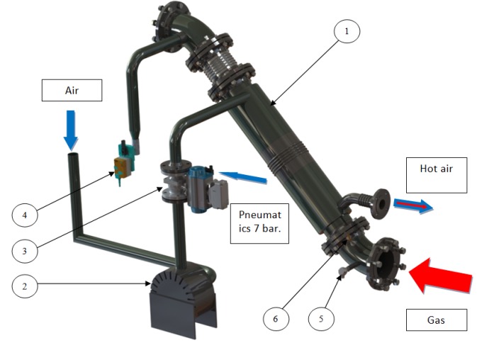
The air preheater is a pipe-in-pipe type heat exchanger consisting of air preheater housing (Item 1), to which is connected an air valve (Item 3), followed by a connected air supply fan (Item 2) and also a connected filter temperature maintenance valve (Item 4).
GAS PURIFICATION MODULE
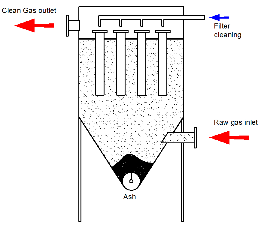
The purpose of the gas cleaning module is to purify the gas from the ash particles present in it. Its housing is made of stainless steel, with 50 mm heat-resistant thermal insulation to ensure heat retention in the filter. Dirty gas enters the filter cone part , moves upwards through the filter elements which are from stainless steel, ash particles drop into the filter cone. The clean gas enters the upper part of the filter where it moves sideways into the gas cooler module. The ash is emptied from the filter housing at the bottom.
WOOD CHIP FEED MODULE
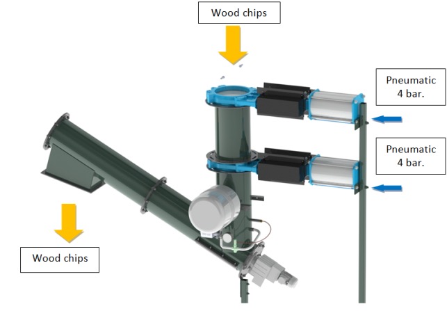
The KOG130_00_SP wood chip feed module is designed for airtight feeding of wood chips into the gasifier, preventing excess air from being sucked into the gasifier, as well as preventing gas leakage into the fuel supply system. It consists of a wood chip level switch which is attached to the upper wood chip conveyor and hermetic pneumatically driven blade valves. The valves require a connection of purified air at a pressure of 4 bar
ASH DISCHARGE MODULE
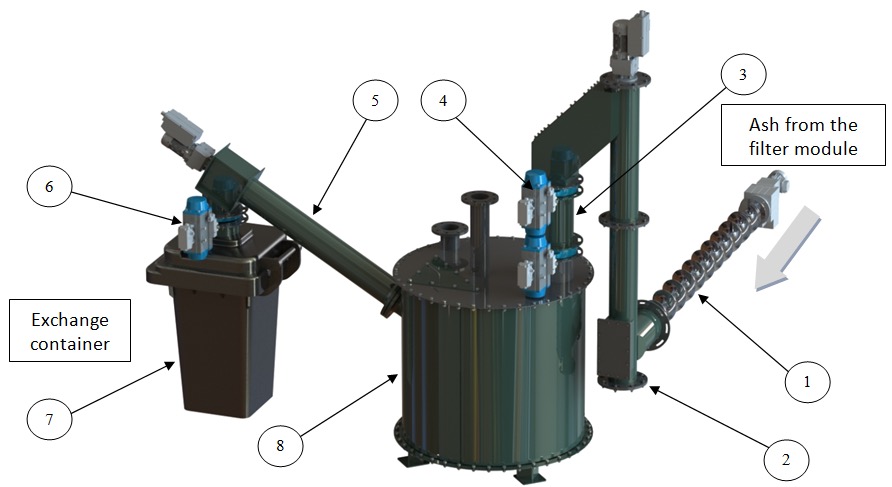
The ash discharge module removes ash from the gasifier system and consists of a horizontal auger (1) which is physically inserted in the filter and moves the ash to the vertical auger (2). The vertical auger is connected to the ash container (8), with the valves (4) located between these items. Attached to the ash container (8) is an ash tank emptying auger connected to the ash container (7).
SAFETY FILTER MODULE
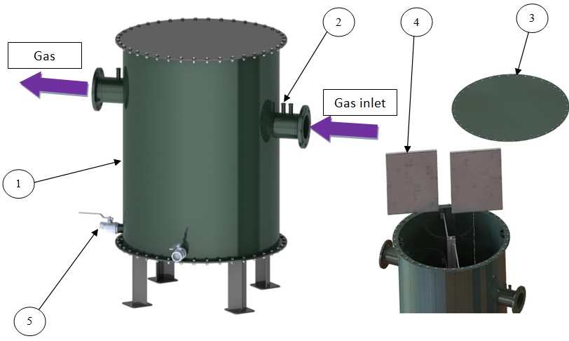
The safety filter consists of a housing containing filter cassettes (4) and a vessel for collecting the condensate is located at the bottom; the condensate must be drained daily through the valve (5). A connection for measuring the differential pressure is installed on the gas inlet and outlet pipes. When the control display shows an error of excessive pressure, the filter element needs to be replaced.

GAS COOLING MODULE
The gas cooler is a pipe-type water-gas heat exchanger designed for cooling gas. Gas from the filter is moved downwards through the upper part by means of engine-produced rarefaction. A condensate collection vessel (Item 3) is located in the lower part. The condensate needs to be drained once a day (during normal operation) by manually opening the valve (Item 5). This operation is also required when stopping the equipment to avoid hardening of the tar droplets in the condensate.
COLD START MODULE
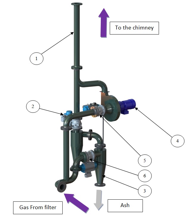
The cold start module is used to remove the flue gases from the gasifier at cold start, as well as to temporarily remove the gas in case of abrupt shutoff of cogeneration stop or during the filter element cleaning procedure. The system consists of DN100 pipes (1), to which cyclones (3), valves (2) and ventilation suction pump (4) are connected.
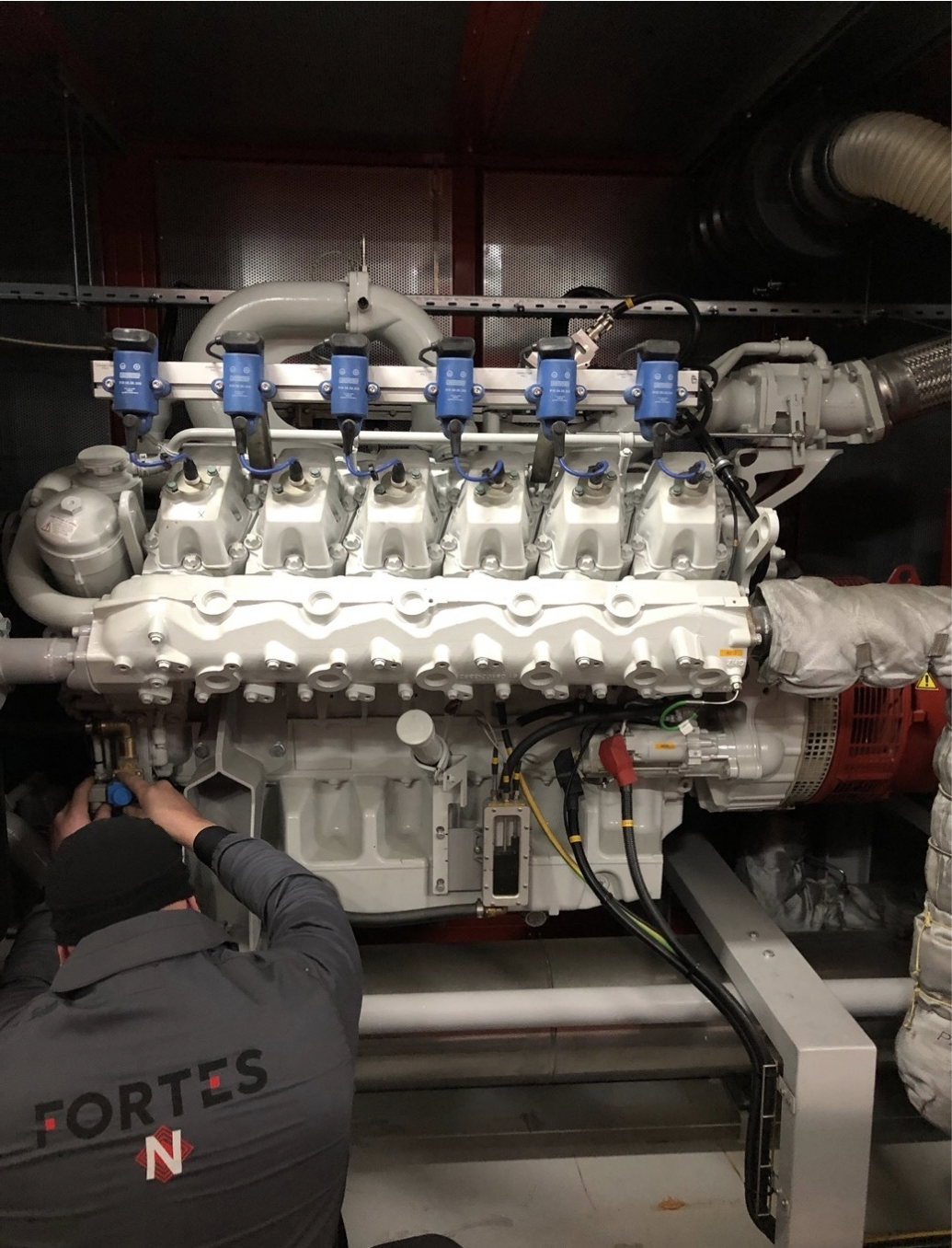
ENGINE WITH GENERATOR
The cold start module is used to remove the flue gases from the gasifier at cold start, as well as to temporarily remove the gas in case of abrupt shutoff of cogeneration stop or during the filter element cleaning procedure. The system consists of DN100 pipes (1), to which cyclones (3), valves (2) and ventilation suction pump (4) are connected.
WOOD CHIP PREPARATION AND SUPPLY
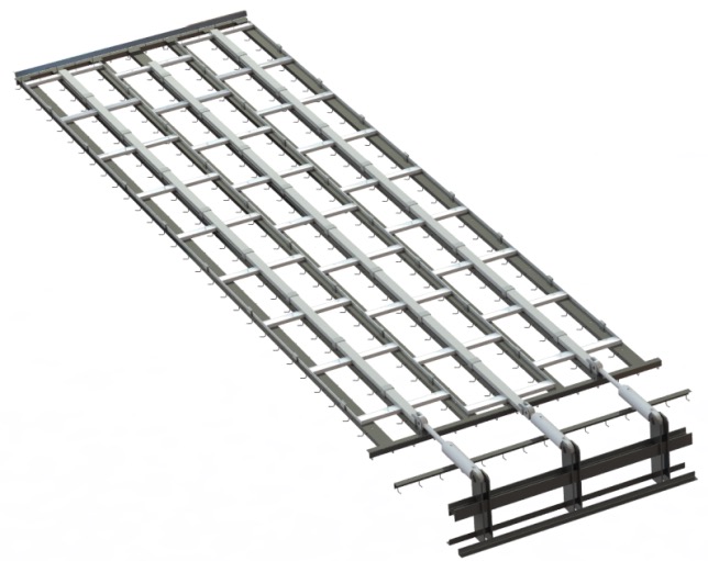
MOVABLE FLOOR FOR CHIP LOADING
Movable floor for chip loading serves as a wood chip storage with an automatic unloading system.
Depending on the customer’s needs movable floor can be created with a different number of movable sliders. The maximum chip load on the floor is 3m. Maximum length of pushers 12m. The maximum density of the material to be loaded is 380 kg / m3. The moving floor sliders are moved by hydraulic cylinders. The set includes a hydraulic oil station whose capacity can vary from 11-36 kW depending on the number of pushers. Concreting works are not included in the offer.
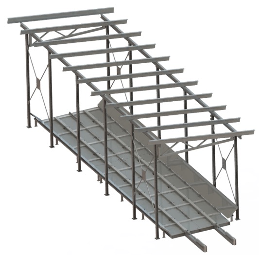
FOLDING CHIP STORAGE
Folding chip storage as an alternative to a movable floor with concrete walls. The movable floor consists of 2 sliders, 14m long. Permissible chip loading height 2.5m and density up to 380 kg / m3. The movable floor is designed to allow a 90 m3 cargo drill to drive in and unload the cargo.
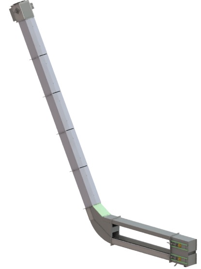
CHAIN CONVEYOR KT100
Chain conveyor KT100 from moving floor to dryer
The conveyor is designed with a side fill. This solution reduces the depth of the concreting pit by reducing the typical problems of groundwater. The width of the conveyor is 450mm, while the dimensions of the moving blade are 310 x 150mm, which are connected with two M80x100 chains. The maximum conveyor capacity is 15 m3 / h, the maximum chip size is G150 and the maximum chip density is 380 kg / h.
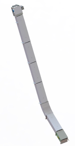
CHAIN CONVEYOR KT200
Chain conveyor KT200 from moving floor to dryer
The width of the conveyor is 450 mm, while the dimensions of the moving blade are 310 x 150 mm, which are connected with two M80x100 chains. The maximum conveyor capacity is 15 m3 / h, the maximum chip size is G150 and the maximum chip density is 380 kg / h.
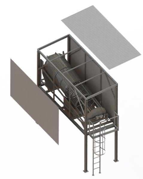
ROTARY CHIPPER LSK
Rotary chipper LSK performs the separation of large and fine fractions. The maximum capacity of the sieve is 15m3 / h. Maximum sieve chip moisture 20%, maximum density 250kg/m3. Engine power 0.55kW. Equipment weight 3.3 tons. The mesh of the sieve can be changed and adjusted to the current situation
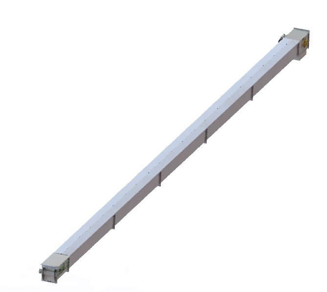
CHAIN CONVEYOR KT300
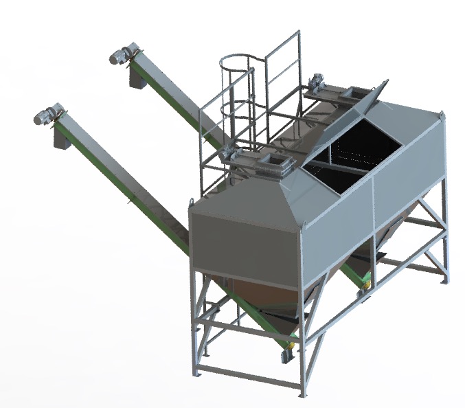
WOOD CHIP DOUBLE HOPPER
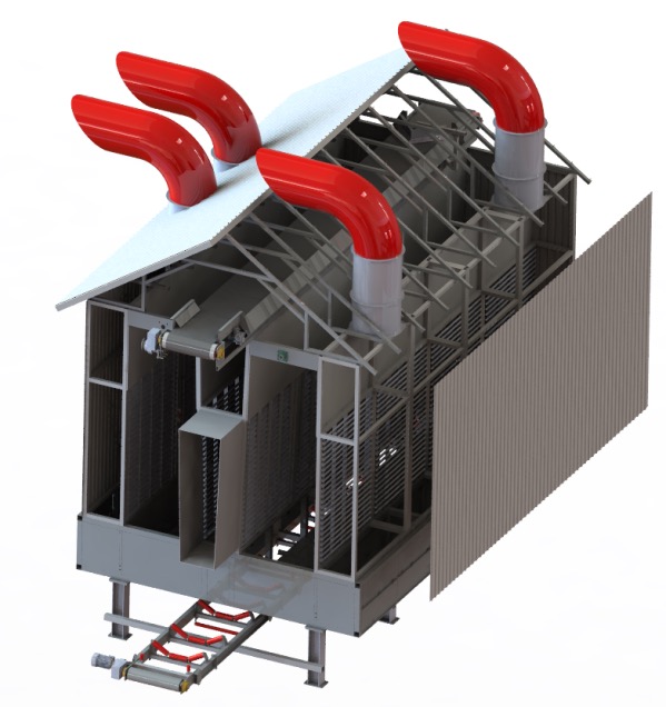
DRYER
SOLUTIONS
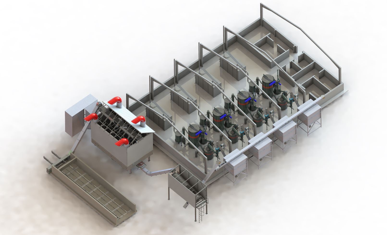
Example of a cogeneration plant with four gasification plants
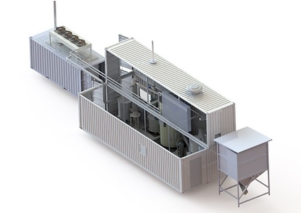
We also offer modular solutions in containers:
Contact Us
To discuss your enquiry, project, service, or support requirements, please get in touch with one
of our amazing teams.
